
TM 10-8145-222-23
0084
REPAIR CONTINUED
NOTE
The control panel assembly is mounted to the power box and will have to be removed
in order to remove the power box. There are four bolts securing the control panel
assembly to the power box. The bolts are accessible from inside the control panel
assembly on the wall closest to the door handle. The nuts are accessible from inside
the power box on the wall closest to the door handle.
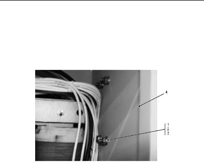
7. Remove four nuts (Figure 8, Item 1), lock washers (Figure 8, Item 2), and washers (Figure 8, Item 3) securing
control panel assembly (Figure 9, Item 3) to power box (Figure 8, Item 4).
Figure 8. Power Box Attaching Hardware.