 |
|||
|
|
|||
|
Page Title:
Compressor Motor Contactor and Electrical Heater Contactor |
|
||
| ||||||||||
|
|
 evaporator coil. These heaters provide the heat
called for by the temperature control to maintain
the required temperature of the conditioned air.
The two banks of heaters provide two ranges of
heating and are manually controlled by placing
t h e selector switch in the proper position
( L O - H E A T or HI-HEAT) to maintain the re-
quired temperature.
b. Inspection. Inspect
elements
for
breaks,
cracks, or other damage.
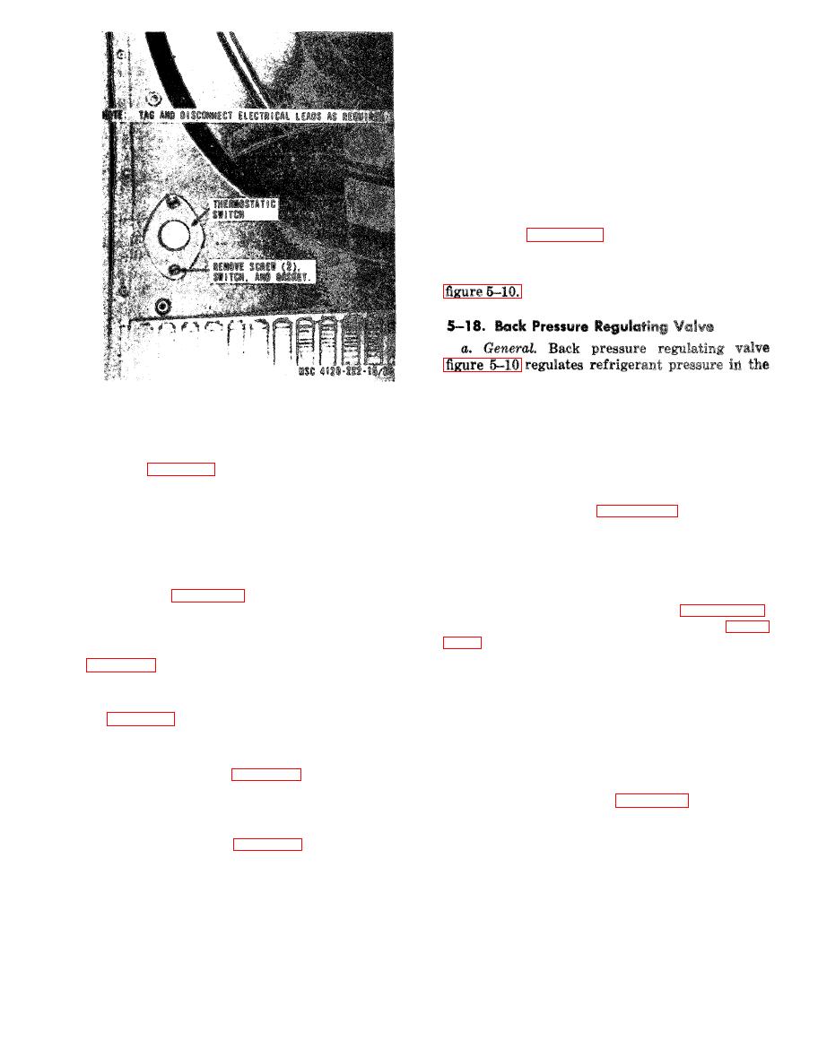
c. Removal. Remove electric heater elements as
illustrated in figure 5-10.
d. Installation. Replace a defective heater and
install in reverse order of removal as illustrated in
evaporator to prevent coil freeze up. Valve is
preset to establish a minimum pressure in the
evaporator of 57.8 psig.
installation.
b. Adjusting. Adjust the back pressure regu-
and install in reverse order of removal as illus-
lating valve by loosening the lock nut at, the top of
trated on figure 5-9.
the valve and turning the adjusting screw.
Tighten the lock nut after adjustment.
d. Inspection. Inspect terminal blocks for
cracks, breaks, or other damage.
the back pressure regulator valve.
Note. Discharge the refrigerant before removing back
Electrical Heater Contactor
pressure valve.
d. Installation. Replace a defective back pres-
a. General. Both Contactors are located in the
sure regulating valve and install in reversing
control box, figure 5-9. A motor contactor starts
order of removal as illustrated on figure 5-10.
the compressor motor and a heater contactor is
Evacuate, and recharge refrigerant system (para
connected to the electrical heaters.
b. Removal. Remove contractors as illustrated on
e. Installation. Replace defective Contractors and
install in reverse order of removal as illustrated
a. General. The electrical circuits in the air con-
on figure 5-9.
ditioner are completed by individual wire leads or
by wire leads laced or enclosed in a loom to fom a
wiring harness. All of the wiring carries code
numbers. When testing, repairing or replacing the
wiring harness or individual wires, refer to the
control box and receptacles.
practical wiring diagrams, figures 1-4. Inspect all
b. Installation. Replace defective (control box
wiring installations for cracked or frayed insula-
and receptacles and install in reverse order of re-
t i o n material. Pay particular attention to the
moval as illustrated on figure 5-9.
wires passing through holes in the frame or
around sharp edges. Repair or replace defective
Caution: Do not remove control box until the
wiring.
circuit breaker linkage is disconnected.
each end. Touch the test probes of a multimeter to
each end of wire. If continuity is not indicated,
a. General. The two banks of electrical resis-
repair or replace wire.
tance heaters are mounted directly behind the
AGO 20053A
|
|
Privacy Statement - Press Release - Copyright Information. - Contact Us |
