 |
|||
|
|
|||
|
Page Title:
Figure 5-5. Pressure-temperature curve. |
|
||
| ||||||||||
|
|
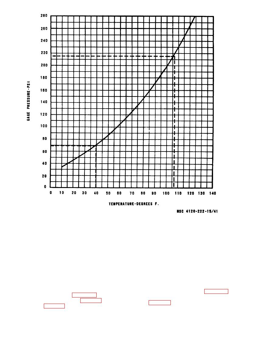 Figure 5-5. Pressure-temperature curve.
Caution: Never adjust the expansion valve
unless it is absolutely necessary. Refer to figure
a. General. A 2.1 ton thermostatic expansion
5-4 and adjust the thermostatic expansion
valve controls the flow of liquid refrigerant into
valves.
the evaporator coil during the cooling cycle. The
one-half ton thermostatic expansion valve func-
Note. Both expansion valves adjust in the same
manner.
tions when the unit is in the bypass cycle. Each
expansion valve is provided with a superheat set-
d. Installation.
ting to insure the operating efficiency of the refri-
(1) Install the thermostatic expansion
gerant system.
valves by reversing the order of removal.
b. Removal.
(2) Replace the dehydrator (para 5-18).
(1) Remove top cover (para 3-15).
(3) Evacuate and recharge the refrigerant
(2) Discharge the system (para 6-1).
system (para 6-1).
(3) Refer to figure 5-3 and remove the ther-
mostatic expansion valves.
a. General. The high pressure cutout switch
c. Adjustment.
|
|
Privacy Statement - Press Release - Copyright Information. - Contact Us |
