 |
|||
|
|
|||
|
Page Title:
Figure 5-6. High pressure cutout switch and hot gas bypass solenoid valve, removal and installation. |
|
||
| ||||||||||
|
|
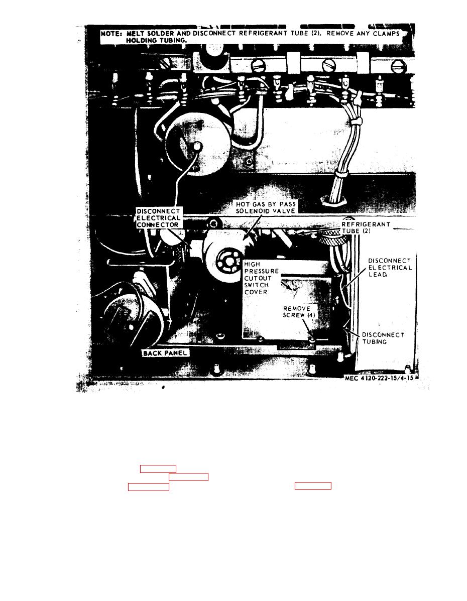 solenoid valve, removal and installation.
no continuity is indicated, push the reset button.
prevents operation of the compressor when the
Replace a defective switch.
system pressure exceeds 445 PSIG.
d. Installation.
b. Removal.
(1) Install the high pressure cutout switch
(1) Relieve the system pressure and dis-
and top cover by reversing the order of removal.
charge refrigerant (para 6-1).
(2) Evacuate and recharge the refrigerant
(2) Remove top cover (para 3-15).
system (para 6-1).
(3) Refer to figure 5-6 and remove the high
pressure cutout switch.
a. General. The hot gas bypass valve is auto-
a multimeter set on the ohm scale. Refer to the
matically operated by the solenoid unit and con-
wiring diagram for points to establish contact. If
5-9
|
|
Privacy Statement - Press Release - Copyright Information. - Contact Us |
