
TM 10-8145-222-23
0028
REPLACE CONTINUED
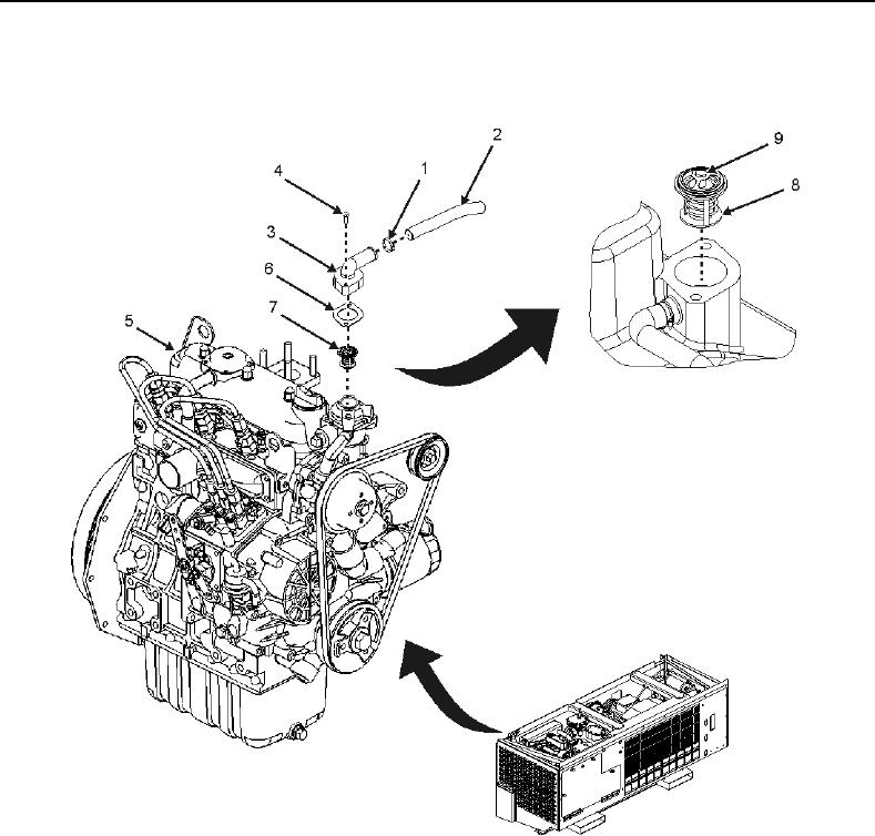
13. Install new thermostat (Figure 3, Item 7) in engine (Figure 3, Item 5) with copper cylinder oriented (Figure 3,
Item 8) toward engine (Figure 3, Item 5) and dome (Figure 3, Item 9) up
Figure 3. Thermostat.
NOTE
When installing thermostat gasket, the bead side of the gasket must be facing up.
14. Line up holes of new gasket (Figure 3, Item 6) with holes on engine (Figure 3, Item 5) and install new gasket
(Figure 3, Item 6) on top of thermostat (Figure 3, Item 7) with bead side facing up.
15. Line up holes of thermostat cover (Figure 3, Item 3) with holes on new gasket (Figure 3, Item 6) and engine
(Figure 3, Item 5) and install thermostat cover (Figure 3, Item 3).