
TM 10-8145-222-23
0035
ADJUST CONTINUED
WARNING
Falling from the roof of the MTRCS can cause serious personal injury or death. Keep
three points of contact on the MTRCS at all times.
3. Access top of MTRCS using roof access provided.
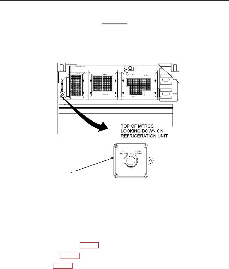
4. Place emergency stop switch (Figure 7, Item 1) in PUSH TO STOP position.
Figure 7. Emergency Stop Switch.
5. Loosen alternator self-locking nut (Figure 8, Item 1), lower mount bolt (Figure 8, Item 2), and V-belt tension
adjustment bolt (Figure 8, Item 3) enough that alternator (Figure 8, Item 4) is free to pivot.
6. Use hand pressure to pivot alternator up in order to put 30-50 pounds tension on new alternator V-belt
(Figure 8, Item 5).
7. Adjust screw (Figure 8, Item 6) on adjusting arm clockwise to tighten V-belt (Figure 8, Item 5) tension.
8. Tighten alternator self-locking nut (Figure 8, Item 1), lower mount bolt (Figure 8, Item 2), and V-belt tension
adjustment bolt (Figure 8, Item 3) (WP 0091, Introduction).
9. Install top-middle panel (WP 0013, Install).
10. Install top-left panel (WP 0013, Install).
11. Place emergency stop switch (Figure 7, Item 1) in PULL TO START position.