
TM 10-8145-222-23
0036
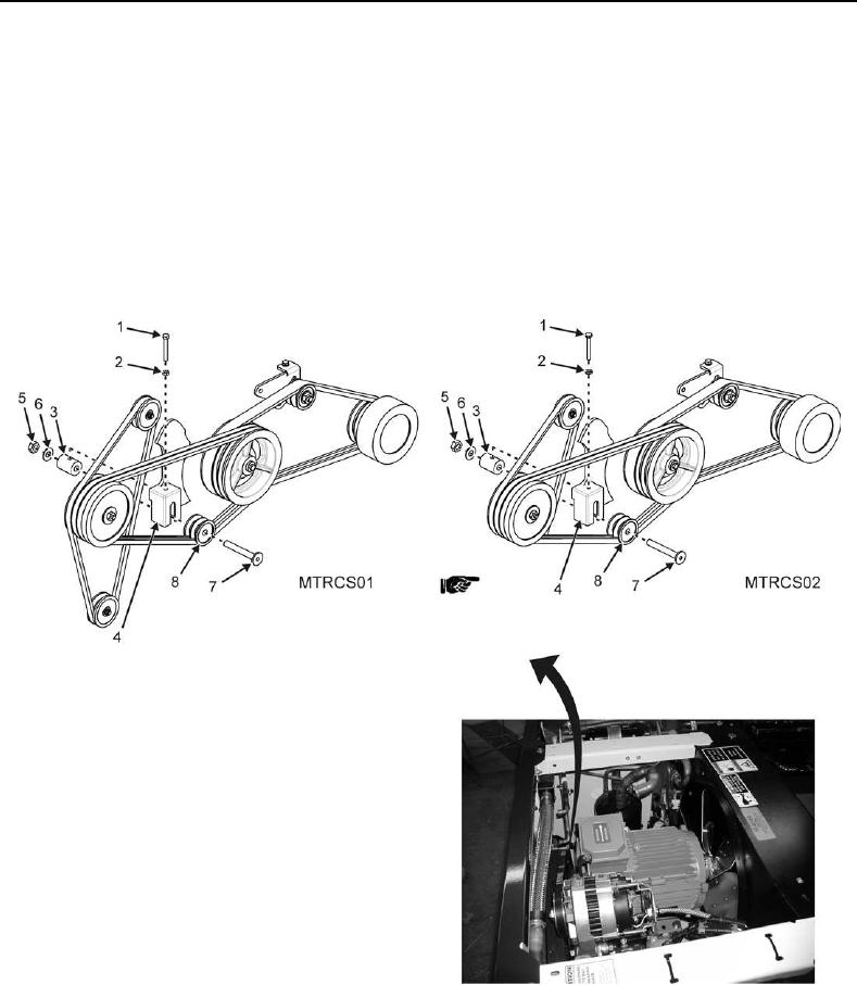
9. Remove idler assembly shaft (Figure 3, Item 7) from bracket (Figure 3, Item 8).
NOTE
The standby motor to compressor V-belts are a two belt set. Always replace both
belts.
10. Remove V-belts (Figure 3, Item 2).
11. Place new V-belts (Figure 3, Item 2) over compressor, idler, and standby motor pulley.
REPLACE CONTINUED
Figure 3. Standby Motor to Compressor V-Belt.