
TM 10-8145-222-23
0061
REPLACE CONTINUED
NOTE
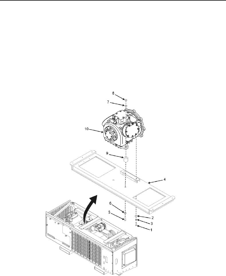
The compressor is secured to the power tray by four bolts. The two forward mounting
bolts have nuts. There are also two spacers between the compressor and power tray
on the forward end.
22. Remove two bolts (Figure 3, Item 1), washers (Figure 3, Item 2), and lock washers (Figure 3, Item 3) securing
aft end of compressor to power tray (Figure 3, Item 4). Discard lock washers.
23. Remove two bolts (Figure 3, Item 5), washers (Figure 3, Item 6), lock washers (Figure 3, Item 7), and nuts
(Figure 3, Item 8) securing front end of compressor to power tray (Figure 3, Item 4). Retain hardware.
24. Remove two spacers (Figure 3, Item 9) located under front of compressor between compressor (Figure 3,
Item 10) and power tray (Figure 3, Item 4). Retain for reinstallation.
Figure 3. Compressor Mounting Aft End.