
TM 10-8145-222-23
MAINTAINER MAINTENANCE
REPLACE
INITIAL SETUP:
Tools and Special Tools
References
Face Shield (WP 0097, Item 20)
TM 10-8415-222-10
Gloves, Rubber (WP 0097, Item 21)
Hoist, Chain (WP 0096, Table 2, Item 2)
Pail, Utility (Metal) (WP 0097, Item 34)
Refrigeration Equipment
Tool Kit (supplement) (WP 0096, Table 2, Item 7)
Service Refrigeration Ordnance
TM 10-8145-222-23P
Tool Kit (WP 0096, Table 2, Item 6)
Equipment Condition
Materials/Parts
Refrigeration unit removed (WP 0059)
Towel, Machinery Wiping (WP 0097, Item 55)
External electrical power disconnected (TM 10-8415-
222-10)
Personnel Required
Utilities Equipment Repairer (2)
REPLACE
Remove
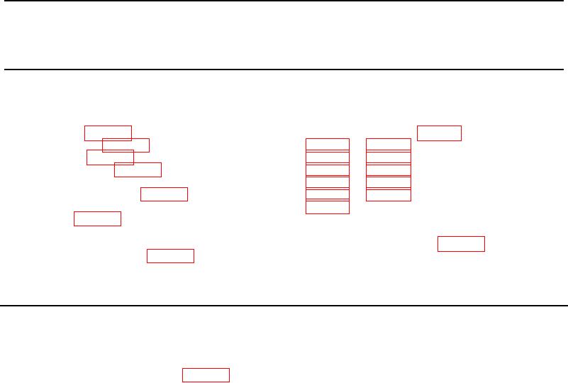
1. Remove front panel assembly (WP 0013, Remove).
2. Remove two screws (Figure 1, Item 1), lock washers (Figure 1, Item 2), and washers (Figure 1, Item 3) from
bracket (Figure 1, Item 4). Discard lock washers.
3. Cut two tie wraps (Figure 1, Item 5) on top bracket (Figure 1, Item 6) securing wiring harness (Figure 1, Item 7).
4. Remove three screws (Figure 1, Item 8) and washers (Figure 1, Item 9) from bracket (Figure 1, Item 6).
5. Remove two screws (Figure 1, Item 10), washers (Figure 1, Item 11), self-locking nuts (Figure 1, Item 12), and
lift bracket (Figure 1, Item 6) from refrigeration unit. Retain bracket for installation.
0061-1