
TM 10-8145-222-23
0071
REPLACE CONTINUED
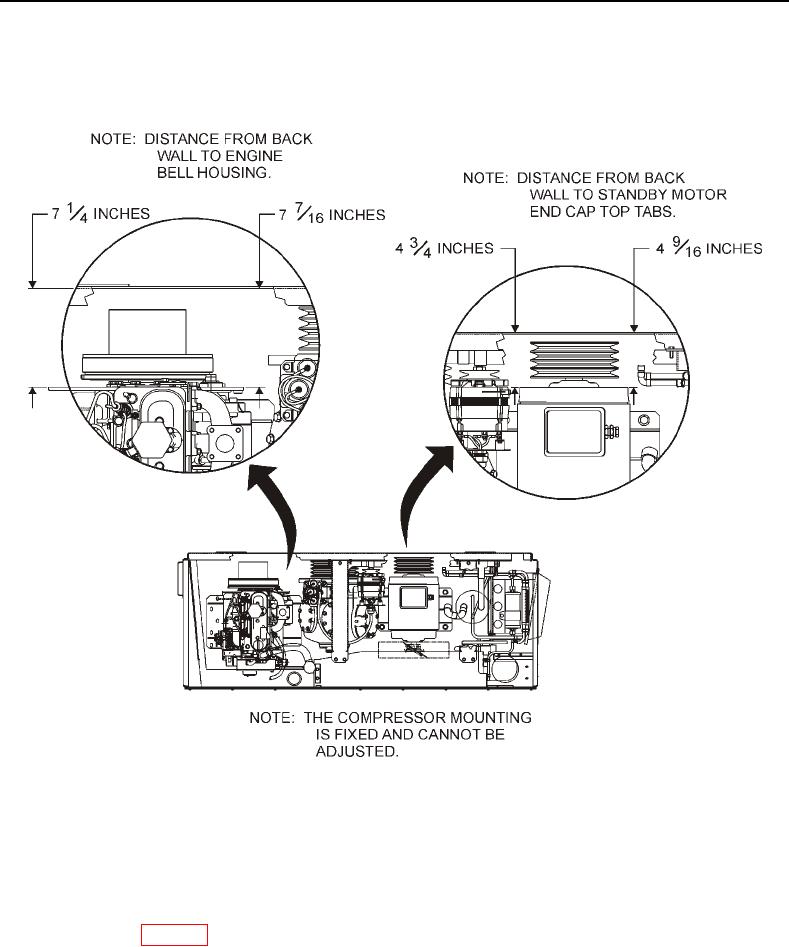
10. Use a rubber mallet to tap diesel engine so that a measurement of 7 1/4-inches is obtained between
refrigeration unit back wall and engine bell housing on outboard side and 7 7/16-inches is obtained between
refrigeration unit back wall and engine bell housing on inboard side (Figure 24).
Figure 24. Alignment Clearances.
11. Tighten five bolts (Figure 23, Item 1) on inboard engine mount bracket (Figure 23, Item 2) to 50 foot-pounds.
12. Tighten five bolts (Figure 23, Item 1) on outboard engine mount bracket (Figure 23, Item 2) to 50 foot-pounds.
13. Check that clearance measurements still exist after tightening all bolts.
14. Install muffler (WP 0039, Install).