
TM 10-8145-222-23
0072
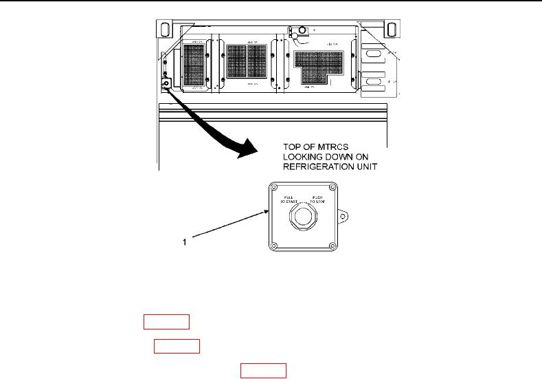
Figure 1. Emergency Stop Switch.
REPLACE CONTINUED
3. Remove top-right panel (WP 0013, Remove).
4. Remove top-middle panel (WP 0013, Remove).
5. Remove standby motor to compressor V-belt (WP 0036, Remove).
6. Remove tensioner adjustment bolt (Figure 2, Item 1) and nut (Figure 2, Item 2) from idler (Figure 2, Item 3) and
bracket (Figure 2, Item 4).
7. Remove lock nut (Figure 2, Item 5) and washer (Figure 2, Item 6) from idler assembly shaft (Figure 2, Item 7).
Discard lock nut.
8. Remove idler (Figure 2, Item 3) and idler pulley (Figure 2, Item 8) from idler assembly shaft (Figure 2, Item 7).
9. Remove idler assembly shaft (Figure 2, Item 7) from bracket (Figure 2, Item 8).