
TM 10-8145-222-23
0084
REPAIR CONTINUED
Replace Selector Switches S1, S2
NOTE
This WP procedure can be used to replace either of the rotary cam switches, S1 or
S2. For this reason, no specific switch will be referred to in the procedure.
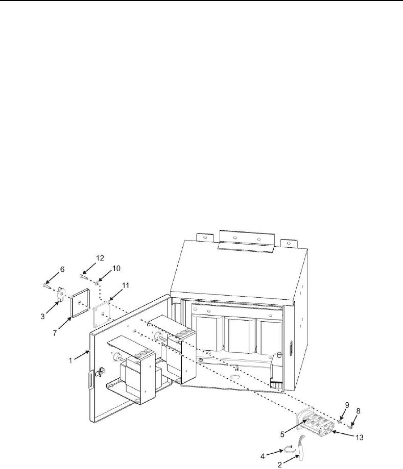
1. Open power box door (Figure 2, Item 1) and secure open.
2. Tag wiring (Figure 2, Item 2) to selector switch (Figure 2, Item 12).
3. Carefully cut and remove any tie straps (Figure 2, Item 4), if required, to gain access to selector switch terminal
screws (Figure 2, Item 5).
4. Remove terminal screws (Figure 2, Item 5) and disconnect wiring (Figure 2, Item 2) from selector switch
(Figure 2, Item 12).
5. Remove one screw (Figure 2, Item 6) securing selector switch knob (Figure 2, Item 3) to selector switch
(Figure 2, Item 12) shaft.
Figure 2. Power Control Box Selector Switch.