
TM 10-8145-222-23
0040
REPLACE CONTINUED
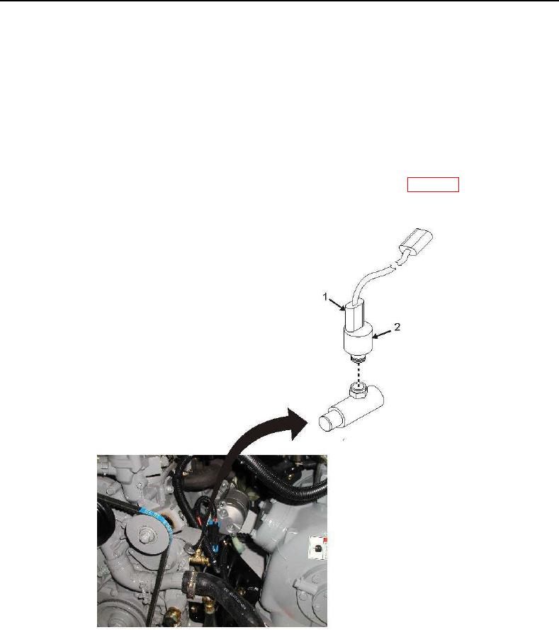
6. Tag and disconnect electrical connector (Figure 3, Item 1) from oil pressure switch (Figure 3, Item 2).
7. Loosen and remove oil pressure switch (Figure 3, Item 2).
NOTE
The oil pressure switch is mounted to the engine block and located slightly behind
the radiator hose.
8. Apply thread sealant to threads of new oil pressure switch (Figure 3, Item 2).
9. Install new oil pressure switch (Figure 3, Item 2) and tighten 11-14 foot-pounds (WP 0091).
10. Connect electrical connector (Figure 3, Item 1) to oil pressure switch (Figure 3, Item 2) as tagged.
Figure 3. Oil Pressure Switch.