
TM 10-8145-222-23
0041
REPLACE CONTINUED
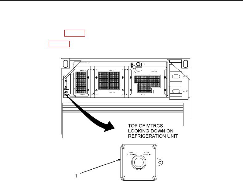
6. Place emergency stop switch (Figure 2, Item 1) in PUSH TO STOP position.
7. Remove top-right panel (WP 0013, Remove).
8. Remove muffler (WP 0039, Replace).
Figure 2. Emergency Stop Switch.
NOTE
To gain access to the two hex screws securing the run solenoid to the engine, it will
be necessary to disconnect one end of the air inlet hose and position it out of the
way.
9. Loosen hose clamp (Figure 3, Item 1) securing one end of air inlet hose (Figure 3, Item 2) to engine air inlet
(Figure 3, Item 3).
10. Disconnect air inlet hose (Figure 3, Item 2) from engine air inlet (Figure 3, Item 3).
11. Tag and disconnect run solenoid electrical connector (Figure 3, Item 4) from engine harness (Figure 3, Item 5).
12. Remove two hex screws (Figure 3, Item 6) and lock washers (Figure 3, Item 7) securing run solenoid (Figure 3,
Item 8) to engine housing. Discard lock washers.
13. Remove run solenoid (Figure 3, Item 8) and gasket (Figure 3, Item 9). Discard gasket.