
TM 10-8145-222-23
0076
REPLACE CONTINUED
Alignment
Alignment of the three major refrigeration unit components (diesel engine, compressor, and standby motor) is
important so that the belts interconnecting these components wear evenly. Misalignment of these three components
could cause belt failure and subsequent system shutdown. Standby motor alignment is accomplished by loosening six
bolts at the base of the standby motor in order to adjust the position of the standby motor.
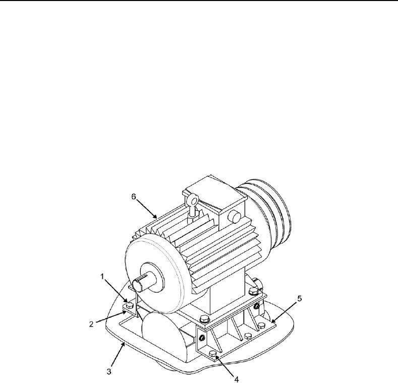
1. Loosen three bolts (Figure 7, Item 1) securing inboard standby motor mount bracket (Figure 7, Item 2) to frame
(Figure 7, Item 3). Do not remove bolts.
2. Loosen three bolts (Figure 7, Item 4) securing outboard standby motor mount bracket (Figure 7, Item 5) to
frame (Figure 7, Item 3). Do not remove bolts.
Figure 7. Standby Motor Mount Bracket Bolts.