• Home
  • Download PDF
  • Order CD-ROM
  • Order in Print
Figure 7. Standby Motor Mount Bracket Bolts.
4. Tighten three bolts (Figure 7, Item 1) on inboard standby motor

TECHNICAL MANUAL FOR MULTI-TEMPERATURE REFRIGERATED CONTAINER SYSTEM
Page Navigation
  729    730    731    732    733  734  735    736    737    738    739  
img
.
TM 10-8145-222-23
0076
REPLACE CONTINUED
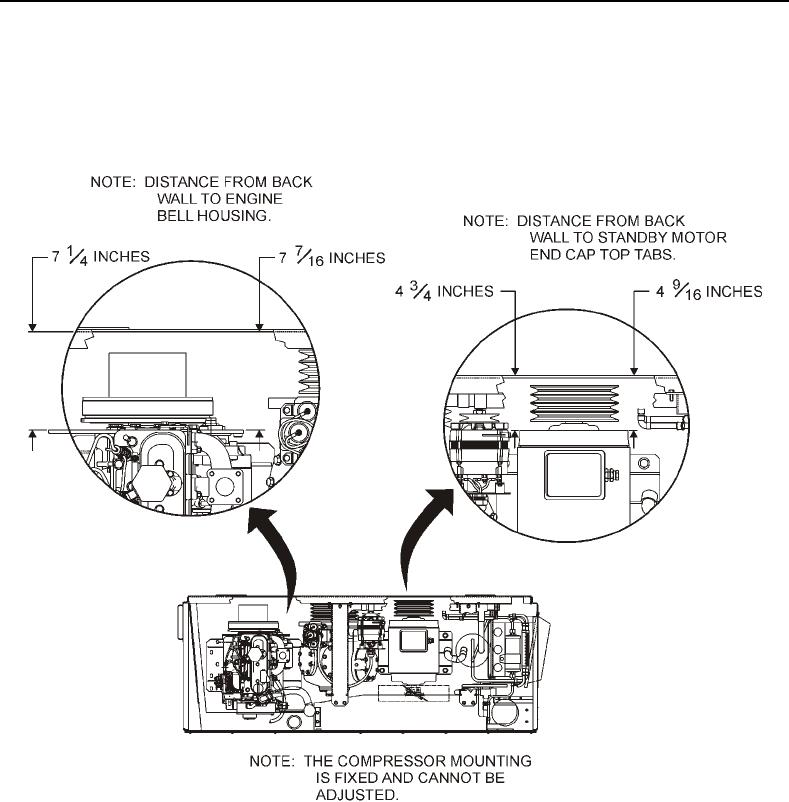
3. Use a rubber mallet to tap standby motor (Figure 7, Item 6) so that a measurement of 4 3/4-inches is obtained
between refrigeration unit back wall and standby motor end cap top tab on inboard side and 4 9/16-inches is
obtained between refrigeration unit back wall and standby motor end cap top tab on outboard side (Figure 8).
Figure 8. Alignment Clearances.
0076-15


Privacy Statement
Press Release
Contact

© Copyright Integrated Publishing, Inc.. All Rights Reserved.