
TM 10-8145-222-23
0084
REPAIR CONTINUED
19. Close control panel assembly door (Figure 6, Item 2).
20. Install cable assembly P2A by pulling cable back into position on storage hooks (Figure 7).
21. Install cable assembly P1A by pulling cable back into position on storage hooks (Figure 7).
22. Close power box door (Figure 6, Item 1).
23. Connect the following electrical connectors as tagged.
P3/J3
P4/J4
P5/J5
P6/J6
P7/J7
P8/J8
P9/J9
P10/J10
P12/J12
P13/J13
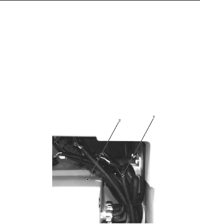
24. Secure wire bundle (Figure 26, Item 1) above control panel (Figure 26, Item 2) using tie wraps.
Figure 26. Control Panel Wire Bundle.
END OF TASK
END OF WORK PACKAGE
0084-27/28 blank