
TM 10-8145-222-23
0079
REPAIR CONTINUED
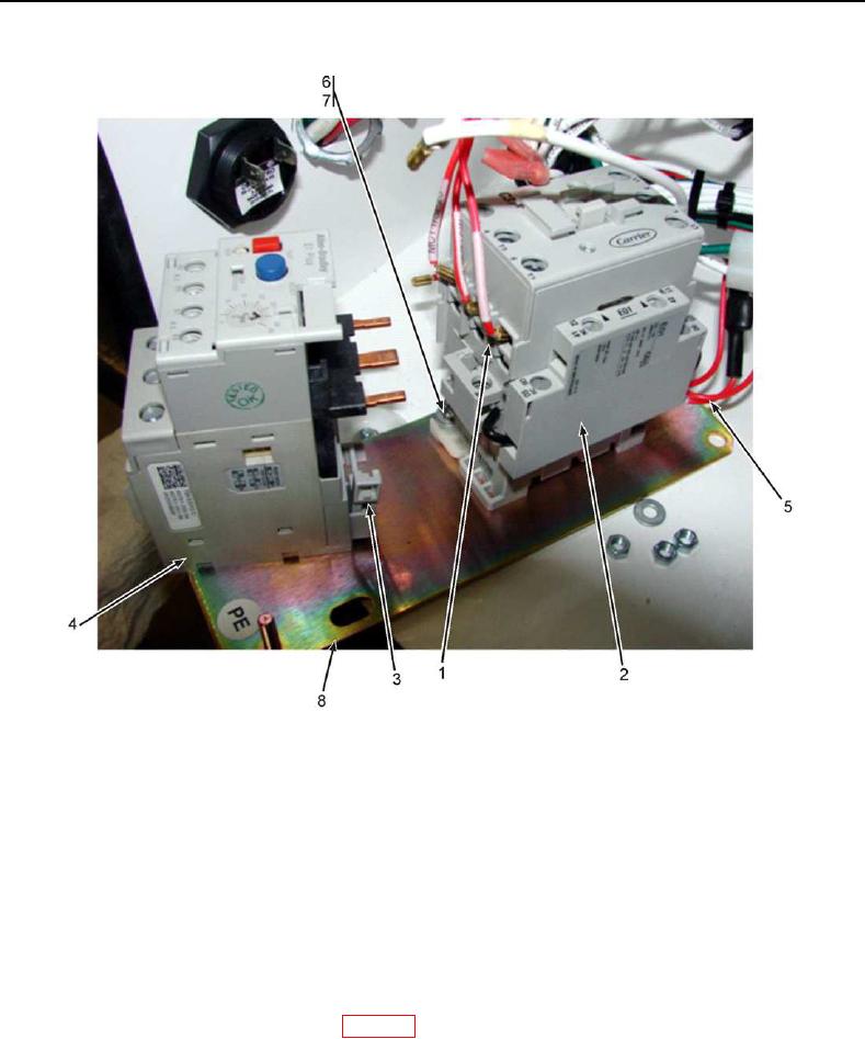
Figure 9. Overload Protector and Motor Contactor.
17. Install ground wire (Figure 8, Item 11) onto panel assembly (Figure 8, Item 8) and secure with nut (Figure 8,
Item 9) and washer (Figure 8, Item 10).
18. Install panel assembly (Figure 8, Item 8) onto mounting studs and secure with three nuts (Figure 8, Item 6) and
three washers (Figure 8, Item 7).
19. Connect three small wires and three large wires (Figure 8, Item 4) onto bottom of the MC (Figure 8, Item 5) as
tagged.
20. Connect six wires (Figure 8, Item 3) onto top of OL (Figure 8, Item 1) as tagged.
21. Set dial (Figure 8, Item 2) to position recorded during removal.
22. Reconnect battery negative (-) terminal (WP 0053, Connect).
23. Start the refrigeration unit and confirm proper operation of the unit per TM 10-8415-222-10.