
TM 10-8145-222-23
0042
REPLACE CONTINUED
NOTE
Before loosening and removing the mount bolts securing the speed solenoid to the
solenoid bracket, scribe a mark where the solenoid is installed so that the
replacement solenoid can be installed in same location.
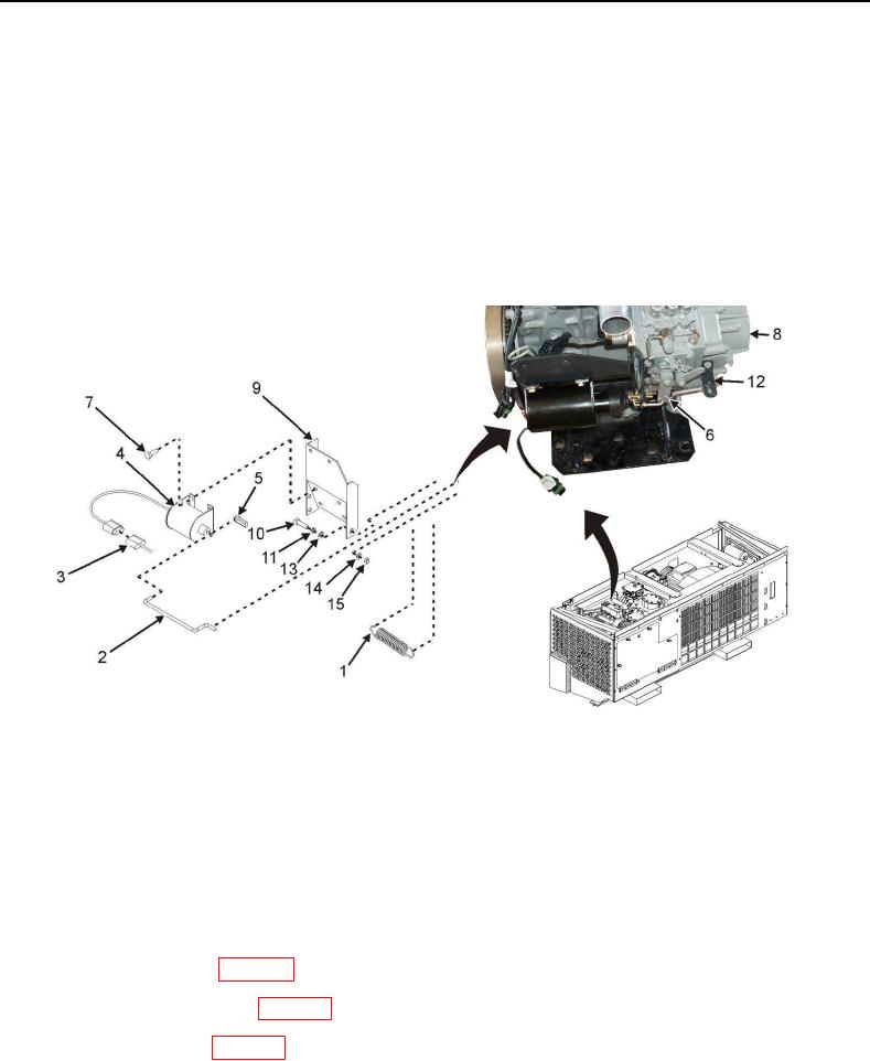
12. Scribe a mark on solenoid bracket (Figure 3, Item 9) where solenoid (Figure 3, Item 4) is installed to be used
during reinstallation.
13. Remove four bolts (Figure 3, Item 7) securing solenoid (Figure 3, Item 4) to solenoid bracket (Figure 3, Item 9).
14. Remove speed solenoid (Figure 3, Item 4).
Figure 3. Speed Control Solenoid Removal.
Install
1. Position new speed solenoid (Figure 3, Item 4) on solenoid bracket (Figure 3, Item 9) where previously installed
solenoid was marked, and secure using four bolts (Figure 3, Item 7).
2. Attach rod (Figure 3, Item 2) to engine speed lever (Figure 3, Item 6) and to new speed solenoid (Figure 3,
Item 4) with clip (Figure 3, Item 5).
3. Connect spring (Figure 3, Item 1) to engine speed lever (Figure 3, Item 6) and bracket (Figure 3, Item 12).
4. Install right-side panel (WP 0013, Install).
5. Install front panel assembly (WP 0013, Install).
6. Install top-right panel (WP 0013, Install).
7. Place POWER ON/DOWN switch (Figure 1, Item 2) on control panel to ON position.