
TM 10-8145-222-23
MAINTAINER MAINTENANCE
RECEIVER AND CHECK VALVES
REPLACE
INITIAL SETUP:
Tools and Special Tools
References
Face Shield (WP 0097, Item 20)
TM 10-8415-222-10
Gloves, Rubber (WP 0097, Item 21)
Refrigeration Equipment
Tool Kit (supplement) (WP 0096, Table 2, Item 7)
Service Refrigeration Ordnance
TM 10-8145-222-23P
Tool Kit (WP 0096, Table 2, Item 6)
Equipment Condition
Personnel Required
Refrigeration unit shut down (TM 10-8415-222-10)
Utilities Equipment Repairer
External electrical power disconnected (TM 10-8415-
222-10)
REPLACE
Receiver
WARNING
Compressor lubricating oil is caustic and can cause severe injury to skin and eyes.
Wear gloves and protective face shield whenever contact with compressor lubricating
oil is possible. If contact with eyes is made, flush eyes and seek immediate medical
attention. If contact with skin is made, wash affected area with soap and water.
1. Recover refrigerant (WP 0014, Service).
2. Disconnect battery (WP 0053, Disconnect).
3. Remove top-left panel (WP 0013, Remove).
4. Remove front panel assembly (WP 0013, Remove).
5. Remove left-side panel (WP 0013, Remove).
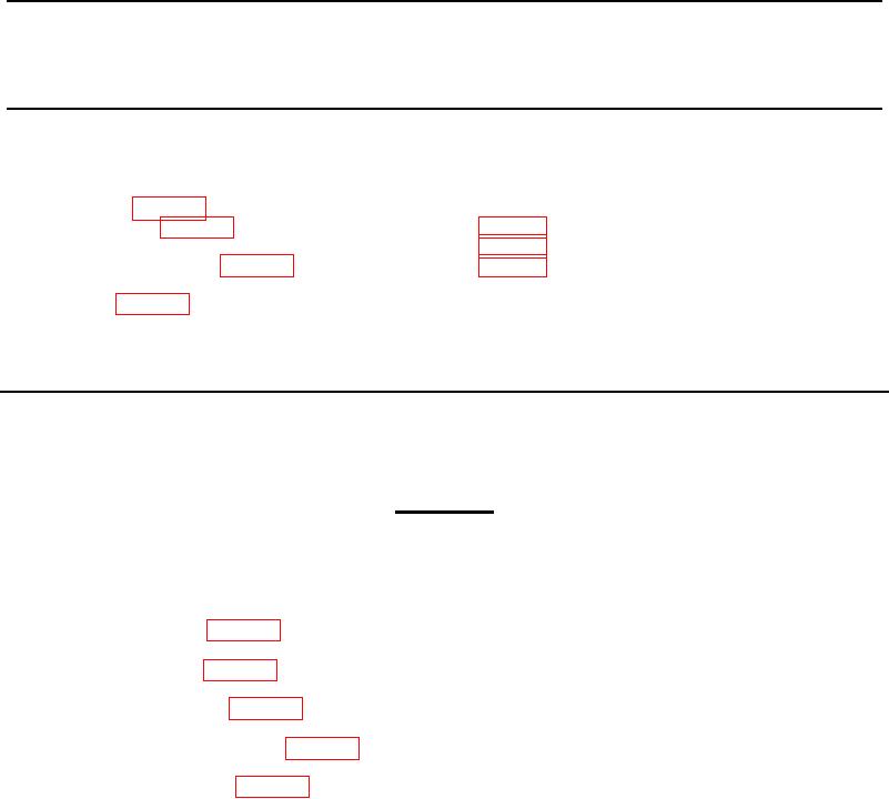
6. Disconnect piping (Figure 1, Item 1) from receiver outlet valve (Figure 1, Item 2).
NOTE
Before removing the 3/8-inch and 1/4-inch check valves from the receiver, make note
of the flow direction as installed to aid in the reinstallation.
7. Disconnect condenser piping (Figure 1, Item 3) from receiver 3/8-inch check valve (Figure 1, Item 4).
8. Disconnect hot gas line (Figure 1, Item 5) from receiver 1/4-inch check valve (Figure 1, Item 6).
9. Remove one nut (Figure 1, Item 7) and washer (Figure 1, Item 8) securing receiver (Figure 1, Item 9) bottom to
bottom panel assembly.
10. Remove receiver (Figure 1, Item 9).
0067-1